News
Oct. 18, 2026
Alumina Ceramic Foam Filters (CFF)
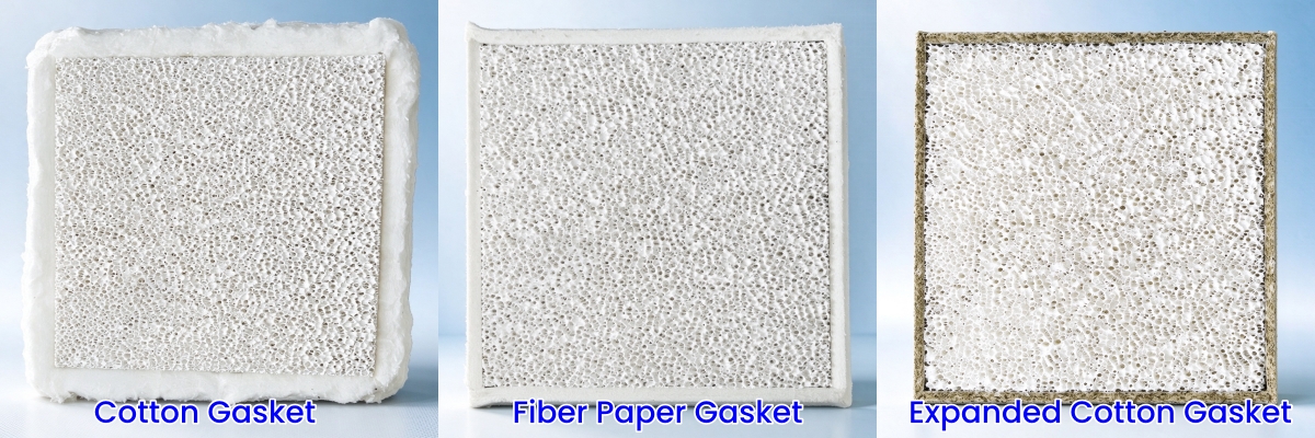
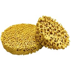
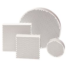
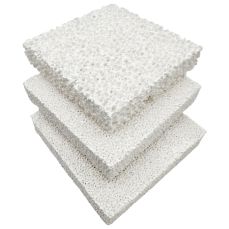
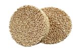
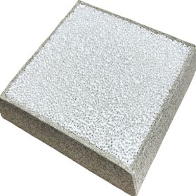
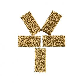
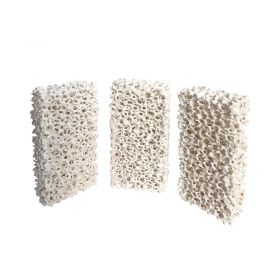
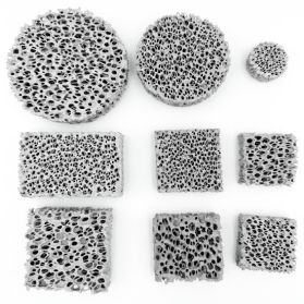
An alumina ceramic foam filter is a rigid, open-cell reticulated ceramic plate installed directly in the gating system — typically at the runner–ingate junction or in a filter box — through which molten aluminum passes before entering the mold cavity.
As the metal flows through the three-dimensional tortuous pore network, non-metallic inclusions are captured throughout the filter depth rather than only on the surface. The filter simultaneously performs two jobs that conventional gating traps cannot do reliably:
1. Depth filtration — oxide films, dross, slag particles, refractory erosion debris, and entrapped flux are trapped inside the pore structure.
2. Flow calming — turbulent, high-velocity melt exiting the sprue is converted into a smooth, laminar stream as it passes through the filter thickness, reducing air entrainment, bifilm formation, and mold wall erosion.
Independent foundry trials and laboratory studies consistently report the following when alumina CFFs are properly specified and installed:
| Outcome | Typical Improvement |
| Non-metallic inclusion reduction | 60–95% removal of entrapped oxide films and slag particles |
| Hydrogen porosity reduction | Up to 70% fewer gas-related pinholes and microporosity defects |
| Elongation / ductility gain | 30–100% improvement in tensile elongation vs. unfiltered castings |
| Scrap rate reduction | Cylinder head scrap reduced from ~5.2% to ~1.8% after PPI upgrade (documented automotive supplier case) |
| Surface finish improvement | Cleaner as-cast surfaces → reduced machining allowance, less grinding and touch-up work |
| Machining tool life | Reduced abrasive wear from hard oxide inclusions → longer insert life and lower tooling cost |
The economic case is straightforward: the filter itself is a low-cost consumable. The returns — lower scrap, higher yield, fewer rejections, longer tool life — typically pay for the filter many times over.
✅Automotive & Light-Vehicle Castings
● Cylinder heads, engine blocks, transmission housings, intake manifolds
● Wheel rims, suspension components, steering knuckles
● Recommended PPI: 30–40 PPI for general production; 40–50 PPI for safety-critical structural parts
✅Aerospace & Defense
● Structural aluminum alloy castings subject to fatigue life requirements
● Aircraft wing components, housings, brackets with strict cleanliness specifications
● Recommended PPI: 50–60 PPI for maximum melt cleanliness
✅Pressure-Tight & Hydraulic Applications
● Hydraulic valve bodies, pump housings, pneumatic manifolds
● Any casting that must hold pressure and pass leak testing
● Recommended PPI: 30–40 PPI
✅General Sand Casting & Gravity Die Casting
● Architectural aluminum profiles, decorative castings, general industrial components
● Secondary aluminum melt with higher initial inclusion load
● Recommended PPI: 20 PPI for high-volume, general-purpose production; 10 PPI for very large castings with high flow requirements
✅Continuous & Semi-Continuous Casting
● Large-format filter plates used in molten metal filtration systems for continuous casting operations
● Filtration capacity up to ~60 tons per 23″ × 23″ filter plate
● Flow rates up to 8.6 kg/s (700 kg/min)
PPI (pores per inch) is the single most important selection parameter.
Higher PPI = finer filtration = lower flow rate.
Match the pore size to your part quality target and casting section thickness.
| PPI | Pore Size (approx.) | Best For |
| 10 PPI | ~2.0 mm | Very large castings, high flow rate requirements, heavy section parts |
| 20 PPI | ~1.0 mm | General sand casting, secondary aluminum, high-volume commercial parts |
| 30 PPI | ~0.6 mm | Most automotive structural castings — balanced filtration and flow |
| 40 PPI | ~0.4 mm | Safety-critical parts, pressure-tight castings, export-quality production |
| 50–60 PPI | ~0.25 mm | Aerospace, fatigue-critical components, maximum cleanliness |
Rule of thumb: When in doubt, step up one PPI grade. The marginal flow reduction is almost always compensated by the scrap reduction and quality gain.
Alumina foam filters are designed for drop-in installation:
● Runner filtration: Place the filter plate across the runner cross-section, secured in a pre-formed filter seat or recess. Seal the edges with refractory mortar or ceramic fiber to prevent metal bypass.
● Filter box / cartridge: For higher flow rates and automated operations, mount the filter in a dedicated filter box positioned between the holding furnace and the mold.
● Orientation: Install the filter with the flow direction perpendicular to the plate face. Do not tilt or place at an angle — uniform flow across the full filter area is critical for consistent performance.
A properly sized filter provides a metal flow velocity of roughly 1–2 cm/s through the filter face — slow enough for inclusions to adhere, fast enough to avoid premature freezing.
Contact Us
+86 158 3011 4065
Guoruiyuan Building, ShengLi North Street, Chang'An District, Shijiazhuang City, Hebei Province, China.
Navigation
Navigation