News
May. 11, 2023
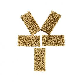
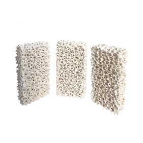
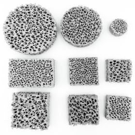
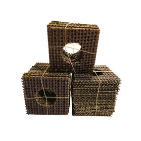
In cast iron, aluminum, steel castings, the slag contained in the metal solution is not easy to clean, it will cause slag holes, pores and other defects and waste, so how to use the casting filter mesh?
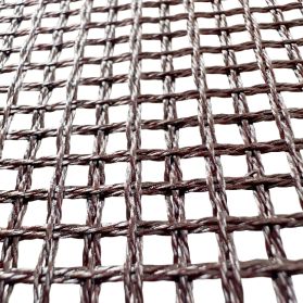
The filter mesh can be cut into any specification, placed on the sprue parting surface of the box pressing, such as the combination of filter net and slag bag, its effect will be better.
However, simply placing a piece of filter mesh in the mold does not guarantee better casting quality. The filter material, mesh opening, filtration area, installation location and support structure must all match the alloy and casting process.
This guide explains how to use fiberglass filtration mesh correctly and avoid common problems such as filter movement, metal bypass, slow mold filling and incomplete castings.
The basic process includes eight steps:
Identify the molten metal and pouring temperature.
Select the correct fiberglass filter material.
Choose a suitable mesh opening and filter area.
Determine the filter location in the gating system.
Prepare a secure filter pocket or support.
Install the mesh flat without gaps or wrinkles.
Pour the molten metal without excessive direct impact.
Inspect the casting result and adjust the system if necessary.
Each step affects filtration efficiency and mold-filling performance.
The first step is to confirm which metal or alloy will pass through the filter.
Standard treated fiberglass filtration mesh is primarily used for molten aluminum and aluminum alloys. High-silica fiberglass mesh is designed for higher-temperature applications and may be used for selected cast iron, copper-alloy and small steel-casting processes when the product is specifically rated for those metals.
Do not use a standard aluminum fiberglass mesh for molten iron or steel simply because the mesh dimensions appear suitable. An incompatible filter can soften, break down or contaminate the casting system.
When requesting a filter recommendation, provide:
Metal or alloy grade
Normal pouring temperature
Maximum pouring temperature
Casting weight
Pouring time
Casting process
Current defect type
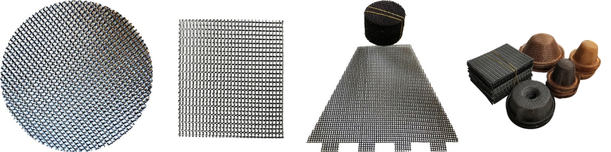
Fiberglass casting filters are available in several forms.
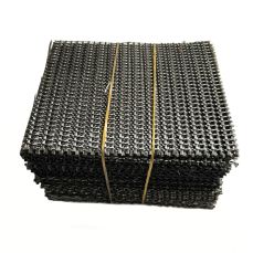
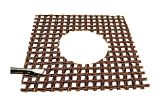
Flat mesh can be cut into round, square, rectangular or custom shapes.
It is commonly installed:
Under the pouring cup
At the top or bottom of the sprue
On the mold parting surface
Inside a runner
Before an ingate
Flat sheets are economical and suitable for many conventional sand and gravity-casting systems.
Rigidized fiberglass filters maintain their shape more effectively than loose mesh.
They can be produced in shapes designed to fit existing filter pockets and reproduce the required metal-flow rate. Pyrotek notes that both the weave and filter shape affect flow performance, so dimensional fit and flow matching are important.
Rigid filters are suitable for:
Permanent mold casting
Repetitive sand casting
Automotive aluminum castings
Wheel and suspension components
Low-pressure casting
Applications where loose mesh may move
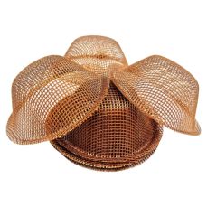
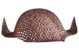
Cap filters are formed into cup, hat, cone or box shapes.
They provide:
A larger effective filtration surface
Improved stability in the mold
Better fit in selected sprue or filter-chamber designs
More slag-holding area than a small flat sheet
Cap filters are commonly used for aluminum pistons, wheels, housings and other repeated production castings.
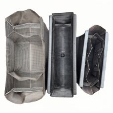
Filter bags are used mainly in molten metal transfer systems, aluminum ingot casting and selected launder or outlet applications.
They may be installed at:
Furnace outlets
Ladle outlets
Transfer funnels
Launders
Ingot or slab casting systems
The required shape should be selected according to the metal-flow path rather than convenience alone.
A finer mesh can capture smaller inclusions, but it also creates greater resistance to molten metal flow.
A filter that is too fine or too small may cause:
Slow mold filling
Reduced metal temperature
Cold shuts
Misruns
Incomplete cavities
Excessive pressure before the filter
Filter deformation or displacement
A filter that is too open may allow larger inclusions to pass through.
The correct selection depends on:
Alloy
Casting weight
Pouring rate
Inclusion size
Required cleanliness
Metal temperature
Filter shape
Effective open area
Gating-system dimensions
The filtration area should normally be larger than the original runner cross-section because only part of the mesh surface consists of open flow area. For high-silica mesh applications, one supplier recommends calculating filter area according to mesh porosity and filtration efficiency rather than matching the runner area directly.
For production castings, the filter size should be confirmed through process calculations, supplier flow data, casting simulation or controlled foundry trials.
Filter location determines how early inclusions are captured and how the filter affects metal velocity.
Common positions include the top of the sprue, the runner overlap and the connection between the runner and ingate.
Placing the mesh below the pouring cup filters molten metal at the beginning of the gating system.
Advantages:
Early removal of larger slag particles
Easy installation
Easy visual inspection before mold closing
Protection for the downstream runner system
Potential problems:
Strong direct metal impact
Premature blockage when the melt contains excessive dross
Insufficient filter support
The pouring stream should not strike unsupported loose mesh directly.
A filter at the sprue base removes inclusions before the molten metal enters the horizontal runner.
This position can also help reduce the energy of the descending metal stream.
It is commonly used for:
Aluminum wheels
Pistons
Automotive components
General sand castings
Gravity castings
The mold should include a stable filter pocket and sufficient flow area.
Runner placement filters the metal before it is divided between different ingates.
This is useful for:
Multi-cavity molds
Long runner systems
Castings with several ingates
Large or complex components
Filtration in the runner can also create back pressure, help the runner fill more evenly and reduce the energy of the metal entering the ingates. Vesuvius testing shows that a filter installed in the runner can produce calmer and more regular mold filling when the filter and gating system are correctly designed.
Installing the filter close to the mold cavity provides final filtration before metal enters the casting.
This position is suitable for:
Precision castings
Thin-wall components
Machined castings
Products requiring high internal cleanliness
Castings with strict surface requirements
Because the filter is close to the cavity, insufficient flow capacity may directly cause incomplete filling.
Rigid fiberglass sprue filters can be used in selected low-pressure aluminum-casting systems.
The filter must:
Fit the sprue accurately
Maintain its shape during the pressure cycle
Provide the required metal-flow rate
Remain securely positioned
Avoid releasing fragments into the metal
Rigid fiberglass filters have been developed specifically to maintain structural integrity through low-pressure casting cycles.
A filter must not allow molten metal to flow around its edges.
Prepare a filter pocket or molded support that:
Holds the filter flat
Prevents sideways movement
Prevents metal bypass
Supports the filter against flow pressure
Does not crush or damage the mesh
Keeps loose sand away from the metal stream
For foam-filter installations, Vesuvius recommends holding the filter securely in a filter print and providing a downstream ledge so the pouring pressure forms a positive seal against metal bypass. The exact dimensions should be adapted to the selected fiberglass filter and mold design.
The filter should cover the entire flow path. A small gap around one side can allow unfiltered metal to enter the casting.
Before closing the mold:
Check that the filter matches the approved material and size.
Inspect it for tears, broken yarns, deformation or coating damage.
Remove loose dust and damaged filters from the work area.
Place the filter in the prepared pocket.
Keep the mesh flat and free from wrinkles.
Ensure the edges are fully supported.
Confirm that molten metal cannot bypass the filter.
Check that the filter will not move when the mold is handled.
Verify the correct orientation for shaped or curved filters.
Close the mold without crushing the filter.
For horizontally installed mesh, the surface should be flattened from the center toward the edges. Loose folds or wrinkles can reduce the effective flow area and produce uneven filtration.
A fiberglass filter removes inclusions, but it does not replace correct melt treatment.
Before pouring:
Remove furnace dross.
Complete the required degassing process.
Control the alloy temperature.
Clean ladles and transfer tools.
Minimize unnecessary turbulence.
Prevent oxide skin from being folded into the melt.
Keep the pouring stream stable.
The molten metal must have enough head pressure to pass through the filter, but the stream should not strike loose mesh with excessive force.
Where possible:
Direct the initial stream toward a pouring-cup wall.
Avoid uncontrolled free fall onto unsupported mesh.
Maintain a continuous pour.
Do not interrupt and restart the stream unnecessarily.
Keep the pouring cup sufficiently full.
Avoid excessive pouring height.
The filter should regulate the flow without becoming the only restriction controlling the entire mold-filling process.
After introducing fiberglass filtration mesh, compare the filtered and unfiltered casting results.
Check:
Pouring time
Mold-filling time
Filter condition
Slag captured by the mesh
Inclusion defects
Oxide-film defects
Surface finish
Internal porosity
Machining performance
Rejection rate
Metal yield
Runner and ingate behavior
If the mold fills too slowly, possible causes include:
Filter area is too small
Mesh is too fine
Metal temperature is too low
Filter is partially blocked
Pouring head is insufficient
The gating system is too restrictive
If inclusions remain in the casting, possible causes include:
Mesh opening is too large
Filter bypass is occurring
The filter is installed too early in the system
Inclusions are generated downstream of the filter
Melt treatment is inadequate
The filter area is overloaded
Changes should be made one variable at a time so the effect can be measured.

The relationship between the cross-sectional area F1 of the casting system and the original cross-sectional area F2 of the casting system without putting the filter net can be expressed as follows:
F1 = F2 / AxB;
A: the porosity of the filter screen, generally 50-60%.
B: the filtration rate of filter screen, generally 60-80%.
Therefore, the cross-sectional area of the casting system is generally 2-4 times that of the casting system without the casting net.
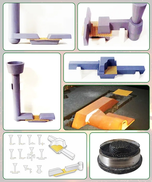
A. Place the filter under the sprue cup;
B. Placed on the parting surface under the sprue;
C. Three different positions on the lap surface of the runner.
When the filter is used, it is necessary to guard against oblique pulling, wear and break. The size of the filter block should be greater than the size of the gate area 20-30mm. Handling, handling should be careful to handle, prevent extrusion, moisture.
Casting filter screen for metal solution filtration purification treatment, remove the slag and part of the gas in the metal solution, improve its quality, reduce the scrap rate of high-quality products. It not only brings objective economic benefits to the majority of producers but also reduces energy consumption, improves labor productivity and product quality.
Fiberglass mesh is generally:
Thinner
Easier to cut into custom shapes
Economical
Suitable for many conventional aluminum castings
Available as flat, rigid or shaped products
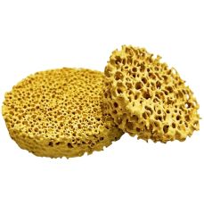
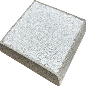
Ceramic foam filters generally provide:
Depth filtration
Greater internal inclusion-capture capacity
Different flow-control characteristics
Options for demanding aluminum, iron or steel applications
Rigid fiberglass filters can be designed to match the flow rate of existing ceramic foam filter systems in selected sand and permanent mold aluminum applications.
The best choice depends on casting quality requirements, alloy, inclusion load, flow rate and production cost.
For more information about filters, please leave us a message, we will reply you as quickly as possible!
Zirconia Ceramic Foam Filter (CFF)
Sep. 17, 2026
Industrial Fiberglass Filter Media: Uses And Benefits
Sep. 17, 2026
Contact Us
+86 158 3011 4065
Guoruiyuan Building, ShengLi North Street, Chang'An District, Shijiazhuang City, Hebei Province, China.
Navigation
Navigation